Page 1 of 1
C19 New pics of console and foredeck
Posted: Fri Jul 08, 2011 9:22 am
by TomD
Ok guys - have a chance to do a little more to my C19. I want to stitch the panels tomorrow and wanted some advice/ approval before going ahead.
If I run a string from the transom (A) to the front mold (E), then B,C and D are about 10mm below the string.
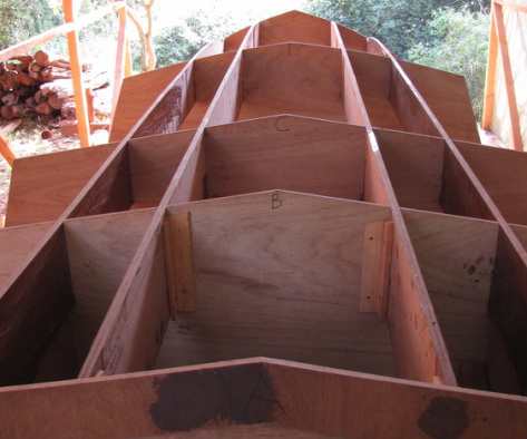
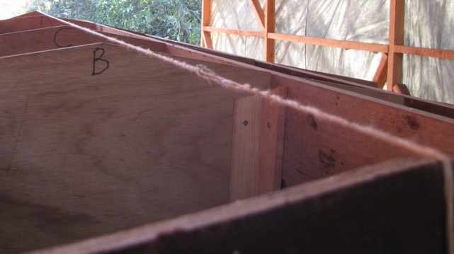
I think that the transom (labelled A) is a little too high. I have not measured the transom from the baseline - but I know the other molds are all pretty close (within 3 mm or so). I think that if I lower the transom, then I could get the string to line up between A, B, C and D,
but I think that the front mold E would be above this. In other words, if I ran a string from A to E (the front), even after lowering the transom, I would not get all the molds in line up.
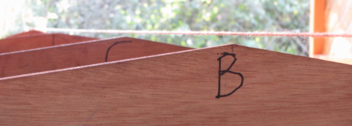
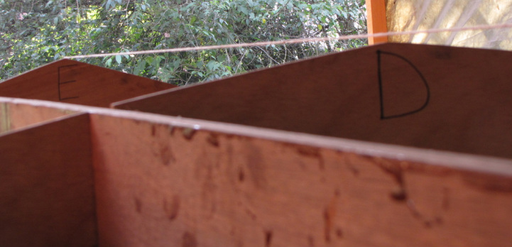
Mold B, C and D seem to be about in line with each other, and by lowering the transom, all 4 of these molds would line up.
So.....
1) Is the front mold (E)
meant to be so high, or have I made a mistake and should I lower it too?
2) I know you are meant to measure everything from the Base Line - but to prevent rocker, or hook (not sure which one is which) surely by ensuring the apex of all the molds are lined up, I will achieve this and get a fair hull? Will this not be easier than tweaking baseline measurements... or am I about to do something dumb?
Re: Preventing rocker - lining up molds at keel of my C19
Posted: Fri Jul 08, 2011 11:35 am
by steve292
Tom,
I would think that the first four molds at least need to be the same level, & would set the transom to acheive this. you may find this cures it all, or you may need to check E's dimensions. 10 mm is to much to be left as an alignment error IMHO.
looks good tho'

Steve
Re: Preventing rocker - lining up molds at keel of my C19
Posted: Fri Jul 08, 2011 12:10 pm
by TomD
Thanks Steve...
OK - I will start by dropping the transom, this is my first move; but are you saying that ideally all the molds should be the same level/height?
E is the one that is confusing me because I have re-measured the base line a bunch of times and it appears to be correct! Same with D,C and B. A, the transom is the only one I haven't measured the baseline for, so I can understand it needs tweaking - its just E that is confusing and am wondering if it is meant to be higher than the rest... confused!!!!
Re: Preventing rocker - lining up molds at keel of my C19
Posted: Fri Jul 08, 2011 2:03 pm
by tech_support
TomD wrote:Thanks Steve...
OK - I will start by dropping the transom, this is my first move; but are you saying that ideally all the molds should be the same level/height?
E is the one that is confusing me because I have re-measured the base line a bunch of times and it appears to be correct! Same with D,C and B. A, the transom is the only one I haven't measured the baseline for, so I can understand it needs tweaking - its just E that is confusing and am wondering if it is meant to be higher than the rest... confused!!!!
transom will be either on the same level of first couple mold forward, or slightly lower. It not uncommon for the fair-body to slightly come up at the transom, it may be so slight you do not notice it. The bottom panels should never warp up at the transom. Something is definately not right.
Re: Preventing rocker - lining up molds at keel of my C19
Posted: Sat Jul 09, 2011 11:09 am
by TomD
I have re-measured all my Base line measurements for the molds and they are all within 1mm of the plans. I checked the transom measurement and lowered it to its base line according to the plans.
Now I can run a string from E to the transom and all the molds line up except D which is about 3-4 mm lower than the string (even though its base line measurement is correct). I guess it could just be that it isn't cut perfectly - should I raise this a tiny bit so it meets the string, or just get on with adding the side panels?
Re: Preventing rocker - lining up molds at keel of my C19
Posted: Sun Jul 10, 2011 1:52 am
by TomD
Could this be why my mold D (as per my photos - transom being A) be slightly lower than the others? Like I said I have double checked all measurements -
http://forums.bateau2.com/viewtopic.php ... lds#p77452
Perhaps I am being a bit too fussy over this issue?
Re: Preventing rocker - lining up molds at keel of my C19
Posted: Sun Jul 10, 2011 4:31 am
by TomD
Here is how the molds line up with the transom lowered. Still a small gap at D - but measurement from baseline seems spot on. Thinking of just raising it slightly till its flush with the string and then forgetting about it? Any advise?

Re: Preventing rocker - lining up molds at keel of my C19
Posted: Sun Jul 10, 2011 4:50 pm
by steve292
TomD wrote:Here is how the molds line up with the transom lowered. Still a small gap at D - but measurement from baseline seems spot on. Thinking of just raising it slightly till its flush with the string and then forgetting about it? Any advise?
Thats what I'd do to be honest. or you could just put the bottom panels on & see how fair you are. If you do that & have no hook or rocker you are good to go. You'll have to shave the frames anyway when you glass 'em in.
How big is that gap 1/8th ? if thats all it is, it's just the width of the saw blade

Steve
Re: Preventing rocker - lining up molds at keel of my C19
Posted: Sun Jul 24, 2011 12:09 am
by TomD
Sorry guys I have been away but ready to get back to work.
The gap is still about 7mm or so - its doing my head in because my measurements to baseline all seem perfect and even if they aren't I can't understand how I would be this far out! I guess all I really need to know is if all the molds are meant to be the same level on the jig or is mold E meant to be higher than D!? Are they all meant to be the same level - which would make sense to me but I haven't built a V-hull before so don't know!?
Perhaps I am missing something - I have rechecked the measurements 5 or 6 times (on different days just in case I am having a midweek Friday afternoon!)
Re: Preventing rocker - lining up molds at keel of my C19
Posted: Mon Jul 25, 2011 1:37 pm
by BassMunn
I remember on my build that the Transom and then the next 3 bulkheads forward were in line but the forward bulkheads did rise up slightly. You often see a bow bulge like that even on production boats.
Also check to make sure your jig hasn't dropped in the centre, your bulkheads might be correctly lined up on the jig but your jig could be drooping from the extra weight - Just a thought
Re: Preventing rocker - lining up molds at keel of my C19
Posted: Mon Jul 25, 2011 5:03 pm
by ericsil
Whatever you do, don't throw any epoxy on that thing until those bulkheads are dead flat with the transom, or even a mm or two higher. The extra tape on the transom edge makes it hard enough to avoid hook without starting that way. You don't want to be able to slide a piece of paper under a straightedge on the back one third of your hull.
Re: Preventing rocker - lining up molds at keel of my C19
Posted: Tue Jul 26, 2011 1:36 am
by TomD
OK - spent all yesterday remeasuring and checking. I am using a centerline string for the measurements so I don't think a sagging strongback is the problem.
I re-measured and the gap was about 4mm - I raised that mold so that all the molds are lined up now. Not sure if this is the correct thing to do but unless someone jumps in and stops me it felt like the easiest solution and someone I feel relieved (if the C19 has a bow bulge Jacques please shout!).
I set the transom up so it is 2 mm lower than the motorwell bulkhead and I have also rebated the ply on the bottom for the tape - so hopefully will avoid hook.
Panels going on today - fingers crossed that I don't find something else to mess with!
Re: Preventing rocker - lining up molds at keel of my C19
Posted: Tue Jul 26, 2011 12:30 pm
by TomD
OK - I have put the bottom panels on and added a frame to my "workshop" so that I can reach the wire ties! I have included photos and would appreciate some tips - seems to have gone together OK....

Just a little concerned that it has lifted off at molds D and E (towards the bow). Pics taken from underside of boat - Is this normal? I know "fairness" is the key - but should they contour the molds?


Also have I made a mistake by tightening the bottom panels before adding the lower side panels?
Here is a view from the transom end.

Can I glue the bottom and lower side panels before adding the top side panels or is it best to get the whole thing "boat shaped first"?
Any pre-fairing tips would be appreciated - we don't have quick fair here and its my least favourite topic...!!

Finally - I am still toying with the idea of a flared bow - will see how it looks tomorrow... If I decide to go for it how many molds back should I start - or should I stick with the front 5 feet or so? Still concerned how I will get it to follow the contour - so will have a good look at it tomorrow before jumping into the deep end! If anyone has any tips on how easily the panels follow a flare (eg CS builders) please let me know....
Finally if its appropriate Shine I would be happy to change this topic to TommyD C19 build...
Re: Preventing rocker - lining up molds at keel of my C19
Posted: Tue Jul 26, 2011 4:19 pm
by Cracker Larry
I can help you with a couple of questions
Just a little concerned that it has lifted off at molds D and E (towards the bow). Pics taken from underside of boat - Is this normal? I know "fairness" is the key - but should they contour the molds?
Fairness of the hull panels is the key. Those frames will get pulled back out, the seams will get a few layers of tape, the bottom glassed over, and then when you reinstall the frames they will fit a lot closer. nothing epoxy won't fill. Carry on
You can change the topic title by going back to the first post and editing it

Re: TomD C19 Build Progress
Posted: Wed Jul 27, 2011 12:56 am
by TomD
Thanks Larry ... that was easy!
Re: TomD C19 Build Progress
Posted: Wed Jul 27, 2011 1:21 pm
by TomD
I will post more pictures of todays progress - but a couple more questions now that I have the side panels on - would really appreciated some feedback as I feel like I have gone round in circles today and had wanted to start gluing!!!
1) Should I attempt to "pull the panels down" so that they sit against frames D and E - there is about a 1" gap between the point of the mold and where the panels join. I tried this earlier today and it made the bow really hard to stitch and seemed to push where the bottom panels meet the side panels off the mold... also I needed loads of stitches on the keel above molds D and E and in frustration with the bow I pulled all these out again and went back to scratch... Do I leave it and if so why did I put so much effort into getting the molds level!!!!
2) Should I start shaving bits off here and there? To be honest it all looks pretty good, where it not for the perfectionist in me not being really irritated that the panels won't sit on the molds I laboured over for so long!!!
3) The transom end for 4 feet or so looks pretty good and the whole thing seems symmetrical - but there is a definite bulge towards the bow above mold E (the 2nd from last towards the bow) and a little at D .... because of it not sitting on the molds. However when I tried pulling them against the mold I got a kink where I was pulling... so I added loads of stitches to keep a straight line which got rid of this but then I couldnt bring the bow together...
4) At the bow the side panels seem to meet a little bit in front of the bow mold - should I squeeze them against the mold or just leave it. There are some positions the panels just don't like.
I have read all the tutorials and numerous posts but can't find anything on the bow bulge or panels lifting off molds for the C19...
Please chime in .... so I can glue tomorrow!!!
Re: Help C19 panels not following molds...to glue or not to glue
Posted: Wed Jul 27, 2011 1:39 pm
by jacquesmm
About the distance between the stern frames/molds and bottom:
this is almost certainly due to the fact that you don't have any gap at the keel, between the panels.
I don't see any gap in the pictures.
You need a gap!
Those panels can not take the proper shape if they push against each other.
You can create a gap either by moving the panels or by cutting a little bit, like 1/4" each side.
The panels must be free to "float". If the fight each other, it will be difficult to get a fair shape.
Solve that problem first: the bottom is what defines the performance of the boat. It must be fair and straight.
PS: I did not see your message because you posted in "non technical messages". I will move this thread to the correct forum tomorrow.
Re: Help C19 panels not following molds...to glue or not to glue
Posted: Wed Jul 27, 2011 2:02 pm
by jacquesmm
Warning: possible confusion . . .
Station names are usually from the bow to the stern. The plans do not name the stations but it looks like you started from the transom.
My answer above is based on C and D being closer to the transom.
From your pictures, it looks like you have that bulge towards the bow between what I would call B and C.
In that case,no need to worry.
I would still make certain that there is a sufficient gap, that should improve the the shape but yes, there is often a bulge there.
Almost none with Okume which bend very easily but Meranti will not take that shape as easily and will get away from the molds a little bit.
You wrote 7 mm: that's fine as long as (as Larry wrote) that the panels are fair.
You asked a question about lining up the height of the molds: use the baseline.
Your mots important consideration before glassing is to have a bottom that is straight and fair.
Straight from the middle station to the transom.
Re: Help C19 panels not following molds...to glue or not to glue
Posted: Wed Jul 27, 2011 3:57 pm
by TomD
HI Jacques, Thanks for the answers - yes I drew the frames starting with A at the transom going fwds....
Here are a few pictures - like I said I have tried to use as few stitches as possible and the panels all came together nicely - but they did not sit well on the molds nearest the bow (marked E and D for me or B and C as you stated). I have included a few pictures. When I did try to get them to sit on the molds they sort of "refused" to do other things like line up at the bow or meet the side panels so nicely. I have only put screws at the transom and only 1 per panel. Most of the panels seem to have a small gap between them.
Finally when you say straight and fair is that mainly at the transom section either side of the keel - as you go fwds towards the bow, the molds start having a curve - so I assume at this point it is not so important.


Still need to work on the bow and bottom to side panels...


View of underside of panels...


Re: Help C19 panels not following molds...to glue or not to glue
Posted: Wed Jul 27, 2011 4:27 pm
by jacquesmm
Now that I know that the problem is towards the boat, I am not worried.
I still see a little overlap between panels close to the bow. If you cut that, it will improve.
For the gap between the molds and the panels, I would not worry as long as it is fair and happens only in the forward half of the boat.
Re: Help C19 panels not following molds...to glue or not to glue
Posted: Wed Jul 27, 2011 5:06 pm
by TomD
Jacques,
Thanks for your help - I guess different woods all bend differently and it must be difficult to predict. I was just a little frustrated as I really made an effort on this build to have everything absolutely perfectly symmetrical, and measured, cut and planed to the line! I can live with a bulge in the front if it wont affect the performance....
Re: Help C19 panels not following molds...to glue or not to glue
Posted: Thu Jul 28, 2011 9:57 am
by jacquesmm
The bulge is small and does not affect performance.
All my settings for max. curvature are based on Okume but even with Okume differences appear due for example to humidity.
It is impossible to predict plywood bending with perfect accuracy but that doesn't matter. A straight run for the planing area and fairness all over is what counts.
Re: Help C19 panels not following molds...to glue or not to glue
Posted: Mon Aug 01, 2011 11:44 am
by TomD
OK - I have glassed the outside since I last posted and have filled the weave with epoxy and microspheres and silica (we can't get quick fair here!). I went over it very lightly with the Random Orbital sander before filling the weave.
A few lessons learned (or re-learned) -
1) I don't think it was worth re-bating all the edges for the tape - I don't think that it was worth the time and effort!
2) I should have spent a little more time fairing before adding the tape and cloth - although I was dying to move fwds I think that I may now have an awful lot of fairing work...
3) I lowered the transom (with the boat upside down) slightly to account for the tape/seams and now I think I have more filling that I expected, to get it level/fair....
Here are some pictures....


Now for all the questions!!!!
1) How fair is fair when it comes to performance at the transom end? How far fwds is the critical bit - I can see a few definite "wavy bits" - and that is not the perfectionist talking!
2) How much can I fill with resin before I should consider putting some cloth in there for strength?
3) Do I look for fairness horizontally, parallel to the keel and vertically parallel to the transom? Any tips on this bit would be great -
Re: C19-outside glassed and starting to fair & yes it needs it!
Posted: Tue Aug 02, 2011 2:14 pm
by wadestep
Some thoughts for you:
1)The 'fairer' the better. I got mine (OB19) to less than the thickness of a US nickle = 2mm. To measure this I got an 8 foot straight edge and held it parallel to the keel, from the transom forward. At the worst spot, a nickle would almost fit under teh straight edge.
2) I had one area that started out as 4 mm indented (2 nickles would slide under the straight edge). I used cloth here 3 layers, each smaller than the last. Everything else I just used fairing.
3) By far the more important direction to get fairness is parallel to the keel. Imagine the boat running at 20 knots, you want the water to be speeding past a flat surface about 8 feet long at the keel. If it is not fair perpendicular to the keel, that's not the direction of water flow while running, and really doesnt' matter nearly as much. for example - people who put on strakes or keels certainly don't end up with a 'fair' hull perpendicular to the keel.
Hope this helps some,
wade
Re: C19-outside glassed and starting to fair & yes it needs it!
Posted: Wed Aug 03, 2011 3:49 am
by TomD
Wade thanks for your help - we are chugging away slowly mainly cos its cold (by our standards and pretty humid) and the epoxy is taking a while to cure.
After the initial enthusiasm/disappointment that everything wasn't as "fair" as I hoped (it never is with me) we are slowly progressing. 2 layers of epoxy mix over the weave and smoothing out the keel ridge so that we have a point of reference.
Gonna take longer than I hoped but a plan falling into place. Will keep you posted...
C19 Progressing Nicely - bottom painted and boat flipped.
Posted: Mon Nov 07, 2011 5:56 am
by TomD
Re: C19-progressing nicely; bottom painted and flipped
Posted: Wed Nov 09, 2011 7:42 am
by TomD
Bolted side panels on and used a square pvc pipe (used to conceal wiring in a house) to play with the sheerline a little bit. I then planed it down to the pencil mark I drew and unbolted it from the boat. I bolted it to the panel for the other side and planed them to match.


Then I glued both panels to the boat, using the original bolt holes I had drilled during dry fitting, and then adding dry wall screws to temporarily squeeze the glue line nicely.
The masking tape is to give me some idea of where my "wood finish" will start.
Hopefully tomorrow the molds can come out!


Re: C19 - flipped and have now added upper side panels
Posted: Wed Nov 09, 2011 8:13 am
by Cracker Larry
Very nice work Tom
Looks great!
Re: C19 - flipped and have now added upper side panels
Posted: Wed Nov 09, 2011 8:34 am
by topwater
Tom the boat looks great

Did you have any problem flipping the boat that way ?
I plan on flipping mine the same way this weekend. Was there much flexing or twisting
of the hull ?
Re: C19 - flipped and have now added upper side panels
Posted: Wed Nov 09, 2011 8:57 am
by wegcagle
Nice job. She is going to be an awesome boat when you are done
Will
Re: C19 - flipped and have now added upper side panels
Posted: Wed Nov 09, 2011 11:01 am
by ericsil
I like it!!!!! Now why didn't I think of that method of shaping the top panel????
Re: C19 - flipped and have now added upper side panels
Posted: Wed Nov 09, 2011 12:17 pm
by cottontop
You have one fine build going. She's going to be a beauty! John
Re: C19 - flipped and have now added upper side panels
Posted: Wed Nov 09, 2011 1:51 pm
by peter-curacao
Those upper panels did you customize them to a higher bow? looking great
Re: C19 - flipped and have now added upper side panels
Posted: Wed Nov 09, 2011 3:01 pm
by TomD
topwater wrote:Tom the boat looks great
Did you have any problem flipping the boat that way ?
I plan on flipping mine the same way this weekend. Was there much flexing or twisting
of the hull ?
Topwater - no problem flipping the hull, just made sure everything was well "spot welded" in place and I reinforced the bow where the bow eye was and just used 3 pulleys to slowly rotate it using the bow eye as the pivot and 2 transom eyes at the back. I didn't reinforce the sheer or anything. The hull does have "lifting strakes" so is quite stiff and held its shape well.
Re: C19 - flipped and have now added upper side panels
Posted: Wed Nov 09, 2011 3:07 pm
by TomD
peter-curacao wrote:Those upper panels did you customize them to a higher bow? looking great
I added about 3 inches to the original panels at the front end and tapered them to the original lines at about half way... I have now shaved quite a bit off though.
I will see how it looks with the molds out and some floorboards in to get an idea of cockpit depth...
Re: C19 - flipped and have now added upper side panels
Posted: Wed Nov 09, 2011 3:26 pm
by peter-curacao
TomD wrote:peter-curacao wrote:Those upper panels did you customize them to a higher bow? looking great
I added about 3 inches to the original panels at the front end and tapered them to the original lines at about half way... I have now shaved quite a bit off though.
I will see how it looks with the molds out and some floorboards in to get an idea of cockpit depth...
I like it I like it a lot
Re: C19 - flipped and have now added upper side panels
Posted: Wed Nov 09, 2011 6:14 pm
by Jerry-rigged
I gotta say, I really like the look of the hull before you added the top side panels...
Hummmm.... (wheels turning....)
Jerry
Re: C19 - flipped and have now added upper side panels
Posted: Wed Nov 09, 2011 6:31 pm
by Cracker Larry
I gotta say, I really like the look of the hull before you added the top side panels...
I was thinking the same thing

Re: C19 - flipped and have now added upper side panels
Posted: Wed Nov 09, 2011 7:53 pm
by gstanfield
I'm thinking it would make a great inshore boat without that top panel, never thought about that. I wonder what it ouwld save on the BOM to build without the extensions
Re: C19 - flipped and have now added upper side panels
Posted: Wed Nov 09, 2011 8:00 pm
by peter-curacao
Cracker Larry wrote:I gotta say, I really like the look of the hull before you added the top side panels...
I was thinking the same thing
Are you both pulling pork? those customized upper panels looks great! if you're both serious in the remarks you made I think you both lost taste in the progress

sorry about that
Re: C19 - flipped and have now added upper side panels
Posted: Wed Nov 09, 2011 8:05 pm
by Cracker Larry
Are you both pulling pork?
That's funny right there

Re: C19 - flipped and have now added upper side panels
Posted: Thu Nov 10, 2011 8:04 am
by TomD
Thanks for all the compliments - I guess its all about what you want the boat for! There are no flats here - so to me the boat looks better with the upper panels on!
A few more pics with the molds removed and the floor boards laid down and my old OD 18 console for "scale". It is nice a roomy inside - and I keep vowing to try and keep it uncluttered! Though I doubt my resolve!


Re: C19 - flipped and have now added upper side panels
Posted: Thu Nov 10, 2011 4:16 pm
by Jerry-rigged
peter-curacao wrote:Cracker Larry wrote:I gotta say, I really like the look of the hull before you added the top side panels...
I was thinking the same thing
Are you both pulling pork? those customized upper panels looks great! if you're both serious in the remarks you made I think you both lost taste in the progress
sorry about that
You miss-understand. I do think the uppers look nice too. But for what I want a boat for, the C19 as drawn is too much boat. However, without the top side panels, it may be darn near perfect.

Re: C19 - flipped and have now added upper side panels
Posted: Thu Nov 10, 2011 5:19 pm
by peter-curacao
Jerry-rigged wrote:
You miss-understand. I do think the uppers look nice too. But for what I want a boat for, the C19 as drawn is too much boat. However, without the top side panels, it may be darn near perfect.
Yea I was a little to fast yesterday commenting your comments sorry about that, to both of you
it's just that I was very enthusiastic about them, I think they look great, maybe better then the original

Re: C19 - flipped and have now added upper side panels
Posted: Thu Nov 10, 2011 5:22 pm
by Cracker Larry
They do look great
I agree. No need to apologize
Re: C19 - flipped and have now added upper side panels
Posted: Mon Nov 14, 2011 10:17 am
by TomD
OK I am looking at installing the chase tubes and I have two 2.5" tubes with long elbows - one for each side. Do you think this will be enough or am I being optimistic. I have enough piping for more, just keen to keep it all fairly simple.
Re: C19 - flipped and have now added upper side panels
Posted: Mon Nov 14, 2011 11:10 am
by Mad Dog
TomD wrote:OK I am looking at installing the chase tubes and I have two 2.5" tubes with long elbows - one for each side. Do you think this will be enough or am I being optimistic. I have enough piping for more, just keen to keep it all fairly simple.
Tom, finally a question I have some experience with. I ran three 2" electrical PVC with the long elbow from the console to the transom. Two on the starboard, one on the port. The reason for choosing two on the right is the capacity to chase all the engine controls; 2 wire harnesses(main and PTT), 2 hydraulic hoses for steering, 2 cables(shift and throttle), oil supply hose, oil tank wire harness, and trimtab control harness(four #14 wires). Everything except the hydraulic hoses and trimtab harness runs through the 2.5" engine rigging tube at the transom but it is a very tight fit. I could not have pulled all those components through one 2.5" chase tube.
Another consideration was to keep all the wiring from the batteries and main buss away from the controls so, the third chase tube on the left carries the main power to the engine and all the electrical accessories at the transom (pumps, blower, lights, etc). Like most of the larger builds I also have chase tubes running forward and from the fuel tank to the transom (I like the fact that the fuel line is enclosed under the sole and I can change it out easily if needed).
MD
Re: C19 - flipped and have now added upper side panels
Posted: Mon Nov 14, 2011 11:51 am
by Cracker Larry
Like MD said, you can't run your electrical and your control cables in the same conduit. Aren't you planning on twin engines? If so, I would double what you have. You might want a couple of smaller conduits to the stern for fish finder transducer, bilge and bait pumps, stern light and such.
Re: C19 - flipped and have now added upper side panels
Posted: Mon Nov 14, 2011 2:38 pm
by TomD
Ok double it is - much less hassle threading things too
Re: C19 - flipped and have now added upper side panels
Posted: Wed Dec 14, 2011 3:44 pm
by TomD
Jacques - or anyone else with the knowledge - I would like to make my gunwales narrower than specified in the C19 plans - is this OK or will I weaken the structure? I think they are 12 inches - I will go for 8...
It will also mean that I reduce the frame width (above the floor boards) - will this be a problem and if so can I compensate by making the frames thicker but narrower?
On a slightly different but related topic, do the frames need 2 layers of biax or is one enough?
Re: Tom D C19 - can I make the gunwales and frames narrower?
Posted: Wed Dec 14, 2011 3:52 pm
by jacquesmm
No problem, you can make them 8".
Above the sole, in the cockpit, one layer biaxial each side is sufficient.
Re: C19 - flipped and have now added upper side panels
Posted: Wed Dec 14, 2011 7:08 pm
by peter-curacao
TomD wrote:Jacques - or anyone else with the knowledge - I would like to make my gunwales narrower than specified in the C19 plans - is this OK or will I weaken the structure? I think they are 12 inches - I will go for 8...
It will also mean that I reduce the frame width (above the floor boards) - will this be a problem and if so can I compensate by making the frames thicker but narrower?
On a slightly different but related topic, do the frames need 2 layers of biax or is one enough?
http://forums.bateau2.com/viewtopic.php ... 40#p211122
Re: Tom D C19 - can I make the gunwales and frames narrower?
Posted: Thu Dec 15, 2011 2:17 am
by TomD
Thanks Jacques - and can I make the Frames narrower (for example the ones that have the rod holder cut outs) and if so how much by?
Its just that if I make the gunwales narrower, I will also want to make the frames narrower to keep them in proportion. Are they an important part of the structure (I am talking above the sole here)...
Re: Tom D C19 - Bouancy Foam Poured
Posted: Thu Jan 12, 2012 12:49 pm
by TomD
A few pics of my progress so far - I know it has been a while. Inside of hull is now glassed and stringers and frames are in. I have put 2 chase tubes each side and modified the transom to 55". I have just finished putting bouancy foam in most of the compartments.
Jacques - Is it possible to move the rear bulkhead for transom well back 6 inches or so? I would only do it above floor level and between the side compartments. I was hoping to gain a little floor space at the back but am worried that:
1) this might affect the structural integrity
2) I won't have enough room to fully tilt the engine up? I know the dimensions are AYBC standard - but at 33 inches from the transom to the bulkhead it seems quite spacious?


Re: Tom D C19 - can I make the gunwales and frames narrower?
Posted: Thu Jan 12, 2012 1:19 pm
by jacquesmm
TomD wrote:
Jacques - Is it possible to move the rear bulkhead for transom well back 6 inches or so? I would only do it above floor level and between the side compartments. I was hoping to gain a little floor space at the back but am worried that:
1) this might affect the structural integrity
2) I won't have enough room to fully tilt the engine up? I know the dimensions are AYBC standard - but at 33 inches from the transom to the bulkhead it seems quite spacious?
You can move it but not remove it.
If you move it back you may not be able to tilt the engine fully and/or may not be able to run the cables without kinks.
yes, I use the ABYC standard and with some engines, you could move it back a few inches.
It depends on the engine. Check your engine and keep in mind that one day you may replace that engine.
Re: Tom D C19 - Floor Glued In.
Posted: Thu Feb 09, 2012 11:16 am
by TomD
I have managed to make a bit more progress on my C19.
The floor is now glued in. You can also see where I have placed 4 backing plates under the floor to attach the T top to at a later stage. Each one is made by welding 4 nuts to a stainless steel plate and embedding this in the floor having reinforced that area. What you see sticking up is the bolts to stop dirt getting into the threads. I am quite pleased by how they turned out.
Also you can see the start of my center console - with curve front edges made as per Peter Curaco's suggestions. The idea being that I can have space to walk around it should I wish to add side lockers to the front compartment...
Anyways here are 2 pictures...


Re: Tom D C19 - Floor Glued In.
Posted: Thu Feb 09, 2012 12:17 pm
by peter-curacao
TomD wrote:
Also you can see the start of my center console - with curve front edges made as per Peter Curaco's suggestions. The idea being that I can have space to walk around it should I wish to add side lockers to the front compartment...
Everything looks great
, I'm flattered someone is using my idea. Why are the sidepanels green?
Re: Tom D C19 - Floor Glued In.
Posted: Thu Feb 09, 2012 3:28 pm
by TomD
Thanks - it worked really well. I should have cut the slots closer than 1 cm but I got the wood to bend nicely in the end. Amazing though how the eye keys in on discrepancies in a curved surface - so ended up with quite a lot of fairing to get them looking the same both sides of the curve.
The side panels are green because I have been mixing pigment in with my epoxy when fairing. Each coat I use a different colour pigment to help see the high and low spots.
Re: Tom D C19 - Floor Glued In.
Posted: Thu Feb 09, 2012 7:40 pm
by tobolamr
TomD wrote:I have been mixing pigment in with my epoxy when fairing
Now THAT is a good idea...
Re: Tom D C19 - Floor Glued In.
Posted: Fri Feb 10, 2012 1:10 am
by TomD
I am sure it came from someone else on this forum - but cant remember who. We dont have quickfair and I dont want to use bodyfiller anywhere so this seems to be the best solution combined with a longboard.
Re: Tom D C19 - Routing hatches!
Posted: Thu Mar 22, 2012 3:39 pm
by TomD
Oops posted this twice so have deleted it.
Re: Tom D C19 - Routing hatches!
Posted: Thu Mar 22, 2012 3:41 pm
by TomD
A few more photos and also what I learned the last couple of days - wish I had paid more attention in geometry lessons! My first attempts with a router have been fun but also a little frustrating - going for the rounded edge on the floor hatch was a lesson in template making patience! Its not perfect but I am reasonably happy with. Square corners are definitely faster - see lid for front locker! Will also need to add to my router bit collection as this might speed things up a little.
Still undecided what I will use my new fancy floor hatch for - considering putting the bilge pump here for when I block the scuppers but haven't really thought it through yet.
Anyways here are a few photos ...


Front locker - square is easy!

The Curaco bend... start of my console....


Close up of brackets for T top embedded in the floor. Bolt hole is completely sealed with an oversized nut welded to a backing plate - so no water can get through to the floor (in theory!)
Re: Tom D C19 - Console shape - which do you prefer?
Posted: Wed Apr 04, 2012 6:47 am
by TomD
Been working hard at the console - it is slowly coming together. I think that it will look good when I round the edges off. The corner pieces are 3x3 quarter ripped African mahogany. I think I will leave them wood with the plywood painted white. Hopefully I can round them into a nice round corner by hand. There is a 6 inch step up to allow me to have a couple of jerry cans of fuel spare under my feet.
I can't decide if I like the straight sided look (first picture) or the one with a cut out and foot rest (second picture).


Also wondering what to do on the backside of the leaning post:
1) A flip up seat
2) A livewell with half round sticking out as a seat
3) A coolbox with cold beer!

Here are a few images with the rubrail clamped on... I was going to do it with 2 layers of 1"x1/2" mahogany but I think that will be very difficult to finish nicely and so am now thinking of only doing 1 layer. Do you think this will be enough? 1/2"x1" rubrail? (Top picture is 2 layers, bottom is 1 layer)


Re: Tom D C19 - Console shape - which do you prefer?
Posted: Wed Apr 04, 2012 8:04 am
by peter-curacao
Hi Tom,
Overall I like it a lot but I don't like the raised section under the steering wheel (keep in mind the pump will raise the wheel significantly), also I'm not sure about the 6 " step (raised sole) I think with a good chop this could be dangerous.
As for the flip up seat, livewell with and coolbox with cold beer! it would be very cool if you could do them all
Boats looking great
Re: Tom D C19 - Console shape - which do you prefer?
Posted: Wed Apr 04, 2012 2:18 pm
by TomD
Peter, Thanks for the comments - at the moment I have a side mount engine control and I dont like them mounted on the side where you can bump into them - hence the box to accommodate this. I am going to mount the steering pump under the lid of the box - so only the wheel is showing.
If/ when I get a top mount control I can just get rid of the box and the steering wheel should be about the same height as it is now (give or take an inch or two).
I raised the floor section 6 inches as it means that I could fit a little more fuel ( there is no point in having an in deck tank here as there is no where to fill it from - so you are better just having removable fuel tanks). Also I like being able to see a little better. I have the same system on my OD and found it really helpful. If I trip over it in chop I should probably not be out boating!
Re: Tom D C19 - Console shape - which do you prefer?
Posted: Wed Apr 04, 2012 2:41 pm
by Prarie Dog
Tom, I like the console with the footrest. The only thing I'd do different is lean the panel in front of the wheel forward at the top. It is vertical enough that, if you mount gauges in it, you will have to stoop over to see them. My console on my GF is like that and it is a pita to see the gauges.
Re: Tom D C19 - Console shape - which do you prefer?
Posted: Wed Apr 04, 2012 2:58 pm
by TomD
Do you mean the thin strip on top of the "steering box" ? I was thinking I might put a couple of drinks holders in it! This is a work in progress - all suggestions welcome! Was thinking of putting the gauges next to the wheel - only have a rev counter and tilt meter!
Still debating where to put the "switches" though...
Re: Tom D C19 - Console shape - which do you prefer?
Posted: Wed Apr 04, 2012 3:53 pm
by Prarie Dog
[quote="TomD"]Do you mean the thin strip on top of the "steering box" ?
Tom, I meant the vertical area in front of that strip. If you're going to use it for beer holders that would work fine. If you put the gauges next to the steering wheel that should work fine too.
Foredeck and locker extension
Posted: Fri Apr 13, 2012 2:39 pm
by TomD
I have decided to extend the foredeck so that people can lie there full length. That was the reason I went with the "curve" on the front console seat. Using a couple of templates made of mdf, I cut out the shapes that I liked. I then cut them out of plywood and adjusted the templates so that they would fit at the floor level. Using 2 layers of 3 mm ply that I glued together I was very happy with the outcome of the curves....
They are now just over 6 foot long and quite comfortable to lie on.
I am now considering changing my locker layout so that I can have 2 long lockers along the sides... Jacques can I cut out part of the bulkhead to allow this and if so how much space should I leave on the sides and above the sole to maintain structural integrity?


Re: C19 Progress - Foredeck and locker extension
Posted: Mon Apr 23, 2012 2:57 pm
by TomD
I am now considering changing my locker layout so that I can have 2 long lockers along the sides... Will there be any structural problems if I cut out part of the original front bulkhead to allow a gap between my new curved lockers and the original one? I think I would cut it just deep enough to allow 2 rods ( I have a few 5 1/2 foot trolling rods) to sit length ways under the lid. I am not planning to cut all the way to the floor level and I will leave at least 6 inches along the edge as the "frame"...
Re: C19 Console and Foredeck Pictures
Posted: Fri Apr 27, 2012 2:19 pm
by TomD
Just a few more pictures of the foredeck and console...
Have also added the sheerclamp on the inside and some of the cleats for the gunwale...


Re: C19 New pics of console and foredeck
Posted: Sun Dec 09, 2012 8:27 am
by TomTom
Progress is going well on my C19 - I havent posted much recently but here is an update.My old user name TomD has been deactivated when I tried to change my email address - so I will post as TomTom till I get that sorted.
I have pretty much finished the foredeck extended lockers - they are just long enough for 6 foot fishing rods.
I have fiberglassed the wooden topsides clear - over a thin fabric - though it neads a few more coats to go completely clear. I am seriously debating just going with white and wood topsides bright finished. Will see how it looks when I loose the newspaper and get a few more coats of resin on there.
I have added the rubrail and hopefully will start working on my mahogany gunwales tomorrow... Quite pleased with the rubrails - I used 2 layers of 1/2 inch by 1 inch mahogany. The first layer I screwed in place, then planed the top so that it was level/parallel with the ground. Then I unscrewed it and turned it over - making the underside parallel now. I glued it in place and when dry I planned it so that it was vertical, using a spirit level as I went. I then glued the second piece on this and it is perfectly vertical and parallel to the floor and ready for the gunwales to sit on top...
A few pics now...


[img]
http://www.weebly.com/uploads/7/6/0/0/7 ... 059560/img]
Re: C19 New pics of console and foredeck
Posted: Sun Dec 09, 2012 8:43 am
by TomTom
Re: C19 New pics of console and foredeck
Posted: Sun Dec 09, 2012 4:35 pm
by cottontop
Boat is coming along nicely. I really like the curvature/workmanship of the fron deck area. I also like the console. Keep up the fine work. John
Re: C19 New pics of console and foredeck
Posted: Sun Dec 09, 2012 7:54 pm
by callyb
Your boat is absolutely beautiful! I think you perfectly nailed all of the aesthetics! Just awesome.
Re: C19 New pics of console and foredeck
Posted: Mon Dec 10, 2012 4:39 am
by sideslippa
Mate I really like your build and all your curvey work. you are an artist..top job.
Re: C19 New pics of console and foredeck
Posted: Mon Dec 10, 2012 5:28 am
by TomTom
Thanks guys for all the compliments --- Ill put some pics when I get the gunwales glued down...
Re: C19 New pics of console and foredeck
Posted: Sun Dec 16, 2012 9:04 am
by TomTom
Re: C19 New pics of console and foredeck
Posted: Sun Dec 16, 2012 9:31 am
by Larry B
OK gunwales are now on and shaped...
And they look great
Re: C19 New pics of console and foredeck
Posted: Sun Dec 16, 2012 9:37 am
by Cracker Larry
They sure do look great
Re: C19 New pics of console and foredeck
Posted: Sun Dec 16, 2012 12:06 pm
by danieloldhouse
Sorry Tom how did you obtained that curved shape? Really nice indeed!
Daniele
Re: C19 New pics of console and foredeck
Posted: Sun Dec 16, 2012 3:11 pm
by TomTom
Hi Daniele - if you mean the curved shape of the front console then I used 2 layers of 3 mm plywood glued together against a temporary mold that was the shape I wanted. When dry the now 6 mm thick plywood laminated retained its curve and I could glass it in place.
If you mean the gunwales, I first got the rubrail how I wanted it - with 2 layers of 1/2 inch by 1 inch mahogany - before gluing down the gunwales made from 1/2 inch by 12 inch mahogany planks - that I joined at the most severe corners. I then used a router and a pattern bit to trim the gunwale to the rubrail.
Re: C19 New pics of console and foredeck
Posted: Sun Dec 16, 2012 4:38 pm
by danieloldhouse
I meant the gunwales, but even the front console is beautiful, I really like that boat. thanks for your quick reply, keep up the good work!
Re: C19 New pics of console and foredeck
Posted: Mon Dec 17, 2012 7:11 pm
by Hope2float
Nice lines and curves. The gunwales looks great.
Dave
Re: C19 New pics of console and foredeck
Posted: Fri Jan 04, 2013 3:12 am
by TomTom
I am having trouble with the thin 80gsm fiberglass that I want to become a clear finish on the topside panels - it remains whitish and there is clearly still air under there - it got worse as the resin (ampreg) dried. The weather has been a little damp and perhaps this has been the problem. I applied a second coat and this still did not fill all the "white" spots. I am wondering whether using a heat gun to try and dry all moisture out from underneath will help before I put another coat on?
Re: c19 scuppers
Posted: Mon Jan 14, 2013 5:20 am
by TomTom
I am now making a mold to make scupper tubes that pass through the rear locker... Due to where the chase tubes come up in the rear lockers I am limited to making my scuppers 1.5 inch by 3 inch oval shaped. Will two of these be enough? Or should I consider putting two more in the middle of the rear bulkhead draining out through the motor well?
C19 with white primer added
Posted: Sun Jan 27, 2013 10:47 am
by TomTom
OK guys some progress pictures to post on my C19 and would love some advise on the paint scheme as it is doing my head in!! Here is the boat with the mahogany gunwales ready to be clear coated and primer applied (Jotun Penguard HB)…
If you recall, there was some sort of contaminant in the thin cloth that I used on the topsides and hence I could not get it to go completely clear. I was going to do away with the idea of having a wood top side (I had wanted to paint the boat similar to the green, white and wood one - in the bottom image) - but then I scrapped the idea for a while, until in a moment of madness I got hold of a lovely wide piece of mahogany and have shaped it to fit over the unpainted section of the hull topside… it would be a veneer (see second picture).
Now I am not sure that I like green now and am edging towards blue...
So am now trying to decide whether or not to go with the mahogany veneer, and then what colour and where? I don't want the boat to look chunky and I do want it to have a "wood feel" but the console and gunwales and transom are all going to be clear coated wood, so don't know if the veneer is overkill!
Also not sure how much to thin it as I think that if I get it really thin it may detract less from the lines!!
Please be brutally honest - do you think it looks better or worse with this piece added?
I have stared at it for so long that I think I have lost perspective!
All advise welcome and the more critical the better!!


Re: C19 New pics of console and foredeck
Posted: Sun Jan 27, 2013 12:20 pm
by TRC886
Finish it to suit yourself, not to suit me
I like the veneer, but I prefer the darker color of the original. If you stain the new piece to match the old, then 'glass it, will it go clear this time?
I like the white, it goes with anything. However, there is too much white right now. I copied your first image and edited it in Paint, adding a black boot stripe just under the side overlap joint. This improved the looks to me, but I didn't like the dark brown wood with the black stripe. Next, I painted the wood black, leaving the rub rail bright, and like that better
I can upload the image if you like, but you can do the same thing I did, and you can play with other colors, color schemes, etc, and find something you like. I'm certain that, whatever you do, it will suit me just fine
Re: C19 New pics of console and foredeck
Posted: Sun Jan 27, 2013 1:30 pm
by TomTom
I would love to see your images - I don't have Paint on my computer and I drown in photoshop but now would be a good time to learn how to do this. The wood won't be stained, I will just clear coat it with resin and I think that should be fine - it won't go as dark as the first image but will be somewhere in between.
Thanks for the advise
Re: C19 New pics of console and foredeck
Posted: Mon Feb 04, 2013 8:07 pm
by TRC886
Knowing that I could recreate them if necessary, I dumped the images. I've tried to recreate them several times over the past week and have not been satisfied with them, but I'll try to PM them to you before the night's out. Just don't expect them to be perfect
Re: C19 New pics of console and foredeck
Posted: Mon Feb 04, 2013 9:13 pm
by TomTom
tomtom30 at live . com all one word ....would be awesome to see what you have come up with, thanks.
Re: C19 New pics of console and foredeck
Posted: Mon Feb 04, 2013 9:30 pm
by TRC886
It didn't work
PM me through this site, or reply to my e-mail which was sent through this site, and I can get your address from that.
Re: C19 New pics of console and foredeck
Posted: Sun Feb 10, 2013 9:45 am
by TRC886
TRC886 wrote:It didn't work
PM me through this site, or reply to my e-mail which was sent through this site, and I can get your address from that.
I replied to you last Wednesday, sending you the pics. Did you receive them

Re: C19 New pics of console and foredeck
Posted: Mon Feb 11, 2013 9:11 am
by TomTom
Thanks for the pic - was very useful. I think that I am going with white - I have added the bump guard and the wood looks really good against the white primer.
Any ideas what the average C19 weighs?
C19 - Out of the shed and fitting the T Top
Posted: Thu Oct 17, 2013 6:18 am
by TomTom
C19 - Out of the shed and fitting the T Top
Posted: Thu Oct 17, 2013 6:20 am
by TomTom
TomD wrote:Ok guys - have a chance to do a little more to my C19. I want to stitch the panels tomorrow and wanted some advice/ approval before going ahead.
If I run a string from the transom (A) to the front mold (E), then B,C and D are about 10mm below the string.
I think that the transom (labelled A) is a little too high. I have not measured the transom from the baseline - but I know the other molds are all pretty close (within 3 mm or so). I think that if I lower the transom, then I could get the string to line up between A, B, C and D,
but I think that the front mold E would be above this. In other words, if I ran a string from A to E (the front), even after lowering the transom, I would not get all the molds in line up.
Mold B, C and D seem to be about in line with each other, and by lowering the transom, all 4 of these molds would line up.
So.....
1) Is the front mold (E)
meant to be so high, or have I made a mistake and should I lower it too?
2) I know you are meant to measure everything from the Base Line - but to prevent rocker, or hook (not sure which one is which) surely by ensuring the apex of all the molds are lined up, I will achieve this and get a fair hull? Will this not be easier than tweaking baseline measurements... or am I about to do something dumb?


